The phenomenon of partial discharge (PD) – the localized breakdown of a section of insulation under electrical stress – can occur in high-voltage electrical equipment found in power transmission and distribution, such as transformers, switchgear, busbars, cables and bushings. Undetected, it can result in total dielectric breakdown and insulation failure, leading to electrical arc flashovers. Conversely, monitoring for PD can provide vital early warning of insulation degradation before catastrophic failure.
Continuous monitoring is crucial, since the effects of partial discharge usually compound over time as the progressive erosion of insulation eventually leads to full dielectric breakdown. Uncontrolled, this can result in sudden, violent and potentially explosive equipment failure.
Even if this worst-case scenario is avoided, such accelerated aging of insulation will necessitate premature replacement of cabling and slash years from the service life of assets, resulting in reduced reliability long before any failure becomes apparent.
Negative consequences of this can include unplanned downtime for utilities and customers, often resulting in regulatory fines – and potential emergency replacement costs running into millions of dollars. Moreover, day-to-day operations can be disrupted by investigations or increased audits – and the resulting damage to the brand and customer trust can impact company valuation.
Why does partial discharge happen?
Partial discharge happens when the electrical field exceeds the dielectric strength of a portion of its insulation, resulting in an electrical spark or arc that (partially) bridges the insulation between conductors. Typically, it is caused by increased electrical stress or field enhancement due to defects in the insulation, and usually occurs over a localized region.
Such defects may be the result of manufacturing faults, poor installation, contamination, aging, or thermal, mechanical or electrical stress. For instance, air pockets in the insulation can concentrate the electric field – meaning that every time the field exceeds the breakdown strength of air, it results in ionization and repeated micro-discharges.
In environments where moisture, dirt, or salt deposits can occur along the surface of the insulation, such contamination can create conductive paths that allow progressive erosion. Meanwhile, aging or mechanical stress can lead to micro-cracks, chemical aging reduces dielectric strength, and thermal cycling may cause delamination.
Furthermore, electrical overstresses can be caused by switching surges, harmonic distortion or even lightning strikes. These conditions increase insulation stress, accelerating existing defects and triggering discharge in weak regions.
Another factor is geometric field enhancement, where sharp points, poor cable termination design, manufacturing defects, or damaged shields can intensify electric fields, leading to hot spots and corona discharges.
Partial discharge pulse characteristics
Electrical pulses that occur as a result of partial discharge typically exhibit the following characteristics: fast rise times, from less than 1 ns to just a few nanoseconds; pulse widths between 5 and 100 ns; and a fast leading edge and an exponential decay tail.
The pulse behaves like a very fast impulse current that is followed by damped oscillation caused by the system’s inductance and capacitance. During discharge, the void capacitance rapidly releases charge, the electric field collapses locally, and a fast current spike flows [see Figure 1].
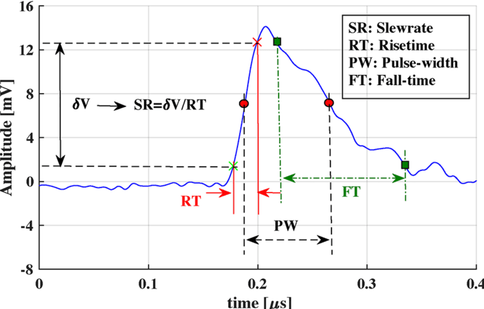
Figure 1. Electrical pulse characteristics of PD, with the void capacitance rapidly releasing charge before the electric field collapses locally, and a fast current spike flows.
Because the frequency spectrum of the pulse extends from hundreds of kilohertz into tens or even hundreds of megahertz, sensors used to monitor for partial discharge must have high bandwidth, with fast ADC (analog-to-digital converter) sampling, as well as carefully designed anti-aliasing filters.
Naturally, for AC systems, such PD pulses usually occur near voltage peaks and typically repeat at similar phase angles each cycle. This results in phase-resolved partial discharge (PRPD) patterns that can be used to identify defects.
Previously, power networks relied on costly, labor-intensive, scheduled offline spot testing that provide only infrequent, periodic snapshots of system health. But as testing and predictive maintenance has evolved, this approach has been replaced with permanently installed, continuous condition monitoring systems using distributed arrays of sensors, thereby helping to significantly reduce the risk of catastrophic failure.
Pulse shape determines many aspects of a sensor network, from the front-end bandwidth required to the apparent charge calculation accuracy, as well as the interleaving mismatch sensitivity. If system bandwidth is not sufficient, peak amplitude is reduced and charge integration becomes inaccurate, meaning small incidents of partial discharge can remain undetected.
Crucially, the required sampling rate of the ADC and the impact of digital filtering are also dictated by pulse shape.
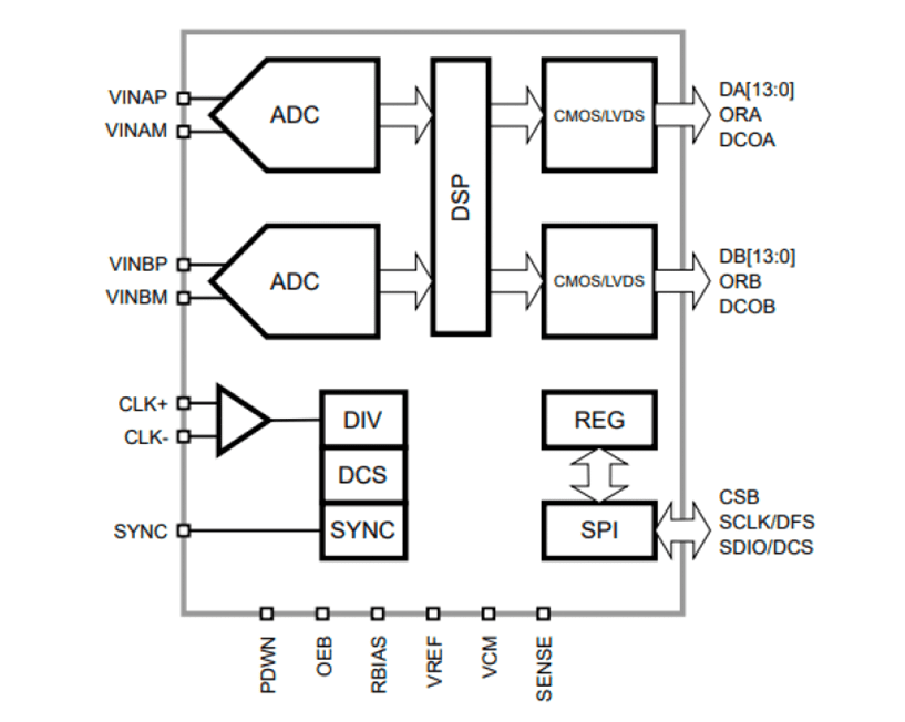
Figure 2. Silanna’s 14-bit, 170 MHz SD1148ET-170 dual channel ADC has an ENOB ≈ 11.7, an aperture jitter ≈ 140 fs and analog input bandwidth ≈ 650 MHz.
Selecting an ADC for partial discharge measurement
The most critical component for characterizing and analyzing these pulses is the ADC – therefore, specifying the correct one is vital. While there may not be a universal ‘best’ ADC, there are steps an engineer can follow to select the most appropriate ADC for their specific sensor network.
ADC selection will depend on the particular sensor type and specific system requirements, with engineers needing to consider several factors including resolution, bandwidth, data rate, power consumption, noise immunity – and cost.
Nevertheless, there are key parameters that the ADC must take into account in order to ensure it accurately captures partial discharge characteristics, including rise time, pulse area, peak amplitude, timing accuracy and repetition pattern. Any distortion of these factors will reduce diagnostic accuracy, potentially allowing early insulation failure to go undetected.
For example, consider a high-frequency current transformer (HFCT) used to monitor multiple partial-discharge locations within a substation that is typically required to measure signals ranging from 100 kHz to 50 MHz. In this case, the HFCT sensor would need an ADC with an effective number of bits (ENOB) greater than 11, aperture jitter that is sub-300 fs, and an analog input bandwidth that exceeds 100 MHz.
To ensure sensor networks are capable of operating in noisy environments, techniques such as oversampling and decimation can be used to improve the effective resolution and signal-to-noise ratio (SNR). Digital down conversion can be used to isolate frequency bands of interest, interleaving correction will help reduce mismatch artifacts and increased timing precision will enhance PRPD pattern accuracy.
FPGAs have typically been used to manage such tasks and enable the low aperture jitter needed for the high SNR required for detecting low-magnitude PD events.
An alternative approach is to undertake these tasks within the ADC via an integrated DSP, as is available with Silanna ADCs, thereby reducing the processing burden on downstream FPGAs to allow for smaller, lower-cost devices without compromising data integrity.
It’s important to note that pulse sensors typically operate in demanding environments, with switchgear cabinets often subjected to very high temperatures and outdoor transformers being exposed to both direct sunlight and freezing winters. Standard commercial ADCs that are rated for operation from -40oC to +85oC may therefore be ill-suited and an ADC that can offer a wider temperature range (potentially even a MIL-TEMP specification from -55oC to +125oC) may be required.
Summary
Partial discharge pulse monitoring is crucial to ensuring the safe and reliable functioning of power networks, but the effectiveness of the sensor networks is entirely dependent on the quality of the data captured. To detect and quantify even the most subtle PD events with precision demands high-bandwidth, low-jitter ADC architectures that can also withstand extreme environments.
Although a universal best device does not exist, by understanding the specific pulses that will be encountered and subsequently prioritizing the right parameters, engineers can specify the correct ADC to create a sound basis for detection and predictive maintenance that will not only prevent catastrophic failure, but also extend the operational life of critical power infrastructure, ensuring the safety, reliability and long-term stability of the grid.
In addition to the above application, Silanna’s family of 10- to 16-bit ADCs are ideally suited for use across a wide range of systems. The company uses a factory-configurable manufacturing process, where specifications are set after silicon fabrication. This reduces risk and enables larger quantities to be produced, leading to lower costs and shorter lead times… as well as preventing the need to end of life niche SKUs. Devices include drop-in replacements for many of the market’s most-commonly used ADCs as well as MIL-TEMP and DSP variants of all devices.
For more information, please visit https://silannasemi.com/plural-adcs/.